in this Raspberry pi gpio tutorial we will experiment with LED and button.
Let’s get acquainted with the general-purpose input/output (GPIO) ports in the Raspberry Pi, take a simple example of connecting the LED and the button (switch) to the GPIO ports, and write a simple Python program that will control the LED’s light (blinking) when help buttons.
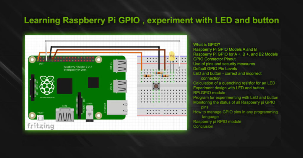
Simple Raspberry pi gpio tutorial for beginners.
What is GPIO?
First of all, let’s see what GPIO is and what it is for. The abbreviation GPIO from English stands for: General-purpose Input / Output – this is the interface. which contains General Purpose Inputs and Outputs, to which you can connect a variety of actuators, sensors, displays, controllers, different modules and different peripherals.
What does the GPIO look like? is a connector that is located directly on the Raspberry Pi board and which contains a set of pins:
- In older models (A and B) – 26 pcs (+ 8 pcs with a separate connector);
- In the new models (A +, B + and B2) – 40 pcs.
The appearance of the GPIO connectors for different raspberry models is shown below.
Raspberry Pi GPIO Models A and B
Fig. 1. Raspberry Pi model B GPIO connector and pin numbering.
In versions A and B, the connector contains 26 pins (P1 header), 8 of which are common GPIO I / O ports, as well as pins for connecting I²C, SPI, UART and power lines + 5V, + 3.3V, GND.
Also, in the earliest versions, you can see a connector on an 8-pin motor (P2 header) – this is the VideoCore JTAG debugging interface, in subsequent versions it was excluded. You can also notice several unsoldered connectors – these are: P3 (LAN9512 JTAG), P5 (8 pins – 4 GPIO, 5V, 3.3V, 2 GND), P6 (to reset BCM2835, Reset).
Raspberry Pi GPIO for A +, B +, and B2 Models
Fig. 2. GPIO interface in Raspberry Pi 2 and pin numbering.
In new versions of the Pi platform, the connector already contains 40 pins (2 rows of 20 pieces each), the first 26 pins (13 in each row) are the same as in earlier versions of the Raspberry Pi, and the remaining 14 pieces are additional GPIOs (9 pieces), GND (3pcs) and 2 pins for EEPROM.
More pins – more options for expanding and using raspberries!
GPIO Connector Pinout Raspberry pi gpio tutorial
In order to use the GPIO connector, you need to know exactly which pin and for what purpose you can use it. Below are the pinouts of the GPIO connectors for different models and different versions of the Raspberry Pi platform.
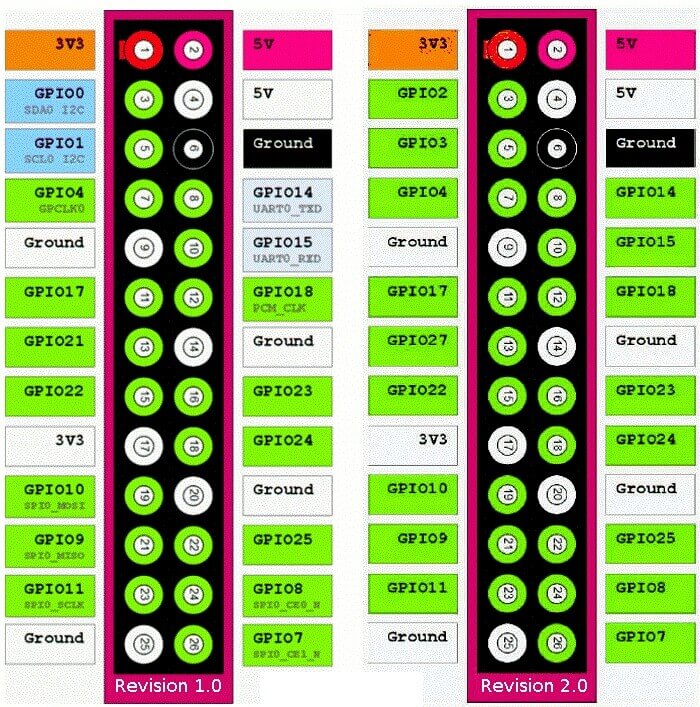
Fig. 3. Raspberry Pi model AB – the location of the pins on the GPIO connector.
It is important to note that for revisions of the PCB 1.0 (September 2012 or earlier) and 2.0, the pin arrangement is slightly different:
- Pin 3 = GPIO0, SDA0, I2C (v1.0) | GPIO2 (v2.0);
- Pin 5 = GPIO1, SCL0, I2C (v1.0) | GPIO3 (v2.0);
- Pin 13 = GPIO21 (v1.0) | GPIO27 (v2.0).
This should be taken into account when designing and modifying devices on platforms with different revisions of printed circuit boards.
Fig. 4. Pinout of the GPIO connector in the Raspberry Pi A +, B +, 2.
Use of pins and security measures
Before you connect something to the pins of the GPIO interface, let’s figure out what voltages can be connected and what we get at the output, you need to remember that:
- At the output of the pins we get 3.3V (not 5V, as many might think);
- The buffers and keys that are connected to the pins are NOT protected against voltage overload;
- GPIO pins can be loaded with a current of 2mA – 16mA;
- Pins with an output voltage of 3.3V can be loaded with a current of not more than 50mA;
- We try to load pins with an output voltage of 5V no more than 500mA (for Model A) and no more than 300mA (for Model B) – why so, I will tell below.
When designing devices that use a large number of GPIO pins, it is imperative to decouple through additional buffer circuits, voltage level converters, electronic keys. What is it for? – to protect themselves raspberries from possible damage (burnout) of buffers inside the chip.
And now let’s see what happens if we connect three LEDs to three GPIO ports and a common 3.3V output, each of which will have a current of 20 mA (ultra-bright LEDs): 20mA*3=60 mA – which is EXCEED of the maximum allowable current 3.3V pin and a slight overload for GPIO pins (20mA per pin).
In this case, to power such LEDs, we need to connect additional keys on transistors or microcircuits to the GPIO pins, which will control the LEDs and will not overload the interface pins.
If we hang on each of several GPIO pins by an LED, then you can connect their common point to the ground, in which case the LED will glow if a high (+ 3.3V) level is present on the pin, and to limit the current to 15 mA, we connect a current limiting LED resistor.
Pins with a voltage of 5V are connected to the main power bus of the 5V board (after the stabilizer), a large load can affect the stability of the platform as a whole, as well as damage the internal voltage regulator + 5V. Care should be taken in their use, the permissible current should not exceed 1A (excluding the consumption of the board itself): 1A – 700mA (current consumed by the model B board) = 300mA.
Actually, the current consumed by the Malinka largely depends on the load of the microprocessor and video processor (the graphic shell requires much more resources than the console mode), as well as on the number of connected devices to USB ports and their consumption. The value of the total current consumption can vary from 250mA to 1A.
Raspberry Pi, like any other sensitive electronics, can be damaged by static electricity. Before work, it is advisable to remove the static charge accumulated on the body, to remove woolen clothes from oneself.
Before soldering the modules and boards, it is advisable to disconnect them from the GPIO connector, it would be nice if it is possible to install with a soldering iron to a voltage of 36V (or lower) using a step-down transformer 220V – 36V, etc.To summarize the security measures:
- Before work, remove static charge;
- It is advisable to solder the electronics with the GPIO connector disabled;
- Do not overload the 3.3V (50mA) pins and do not short-circuit them directly with other pins;
- Do not overload the 5V pins (300-500mA) and do not short-circuit them directly with other pins;
- Exclude the flow of current greater than 15mA through the GPIO pins;
- Exclude voltage over 3.3V to the GPIO pins;
- Connect directly to the Raspberry Pi no more than 3 LEDs (up to 15mA each);
- Carefully check the correct connection before applying power to the circuit and the raspberry.
Default GPIO Pin Levels
It would seem, why did I put this question in a separate subtitle, everything is clear here … it’s actually not so simple, be careful about the information below , it should be taken into account when designing your future devices.
After the Raspberry Pi is turned on and the Linux operating system is loaded, the GPIO pins are set to low (0V), and so on until some program or script changes the state of the ports.
This information is taken from the documentation, and it is also confirmed by probing the state of the pins with the help of a tester. Everything is logical and convenient here – after switching on, all pins are set to “0”, later we set and switch the states of the necessary pins, thus we build our hardware-based applications based on Raspberry Pi.
And everything would be fine if it were not for a small BUT … Its essence is that from the moment power is supplied to the platform and until the drivers are initialized in the OS, high levels ( 3.3V) can be present on arbitrary pins for a short time .
This point must be considered when designing circuits connected to the GPIO!
Sometimes a good solution may be to reserve one GPIO pin to control the power supply circuitry for the electronics and actuators, in which case the power supply to the electronics will only come after Linux boots up and your program script supplies a high level to the circuit power control pin.
More detailed information on how GPIO works on the Raspberry Pi platform can be found in the documentation for Broadcom processors (see links at the end of the article).
LED and button – correct and incorrect connection
On many resources on the network, you can find articles and tutorials for beginners on the raspberry and GPIO, in which LEDs and buttons are connected in different ways. Some switching schemes, even if they are operational, can be dangerous for raspberries. Now I will give a couple of examples and briefly explain why.
Fig. 5. Correct and incorrect connection of the LED to the Raspberry Pi.
As can be seen from the figure, a current-limiting (quenching) resistor is present in the correct connection, which limits the current through the LED and pin GPIO4 (for example). With a direct connection without a resistor, the LED will receive a voltage of 3.3V, which is clearly more than the norm for LEDs (2-3V). A forward voltage of this magnitude will cause a sufficiently large current in the 50 + mA circuit, which can lead to burnout of the LED and failure of both a separate GPIO buffer and the processor as a whole.
Fig. 6. Correct and incorrect connection of the button to the Raspberry Pi.
You need to connect the button to the GPIO using the reference voltage and restrictive resistors. Someone may ask: what kind of connection is this redundant, that you need two more resistors to connect the button, is it possible to get by with one button? – No you can not.
And here’s why: in the case of a direct connection, there is a chance to burn the used output, since during system initialization (raspberry boot) or incorrect setting of port modes (configured as OUTPUT) + 3.3V can go to the used pin, which in turn will cause the button to close port short circuit to GND ground.
In the resistor circuit, we get this:
- While the SW1 button is not pressed, a high level of 3.3V is set through the resistors R1 and R2 at the port input;
- When the SW1 button is closed, a current equal to I =U/R =3.3V/10000Ohm=0.33mA will go through the resistor R1 and the button, and a low level of 0V will be set through the limiting resistor R2 and the button at the port input;
- If the port pin is set incorrectly, no current will flow to the 3.3V output through the R1, R2 chain (3.3V = 3.3V), and when the button is pressed, a current equal to R = 3.3V/750Ohm will flow through R2 and SW1 =4.4mA, which is a safe value and does not damage the circuit and port GPIO.
Resistor R1 can be set to a resistance of 10 kOhm – 20 kOhm, and for a resistor R2 of 600 ohms – 2 kOhm, everything should work confidently.
Those who connect the button as in the crossed-out figure # 6 are extreme people who consciously or unconsciously try their luck! No need to spare the resistors, it is better to install approximately 1K for each pin across the resistor and configure the circuit for reliable operation with such resistance values than then, in case of an error, pay the price of the whole Raspberry pi board!
Calculation of a quenching resistor for an LED
As a rule, for experiments with LEDs, a quenching resistor of 270-600 Ohms will be enough. With more resistance, the LED will glow a little dimmer, and with less – brighter.
For a more accurate calculation of the resistance of the quenching resistor (with pyatnias from the 3.3V line), we use the formula:
R = (3.3V – Ud) / Id,
Where:
- R is the resistance of the quenching resistor;
- Ud – operating voltage of the LED;
- Id is the working current of the LED.
I will give here typical voltage values for LEDs of different colors:
- red – 1.8 … 2V;
- yellow and green – 2 … 2.4V;
- white and blue (bright) – 3 … 3.5V.
The operating current of the LEDs, depending on the type, can fluctuate within 10-25mA. For more accurate calculations, it is better not to be too lazy and clarify the parameters of a particular LED in the directory. In our case, for experiments, a current of 10-15mA will be sufficient and safe.
For example, take the AL307 domestic red LED and calculate a quenching resistor for it at a current of 10 mA:
R= (3.3V – 2V)/0.01A =130Ohms.
When the resistance of the quenching resistor is 130 Ohms and the voltage is 3.3 V, the LED will shine quite brightly. You can experiment with resistance, most likely that at a value of 300 Ohms, the brightness of the glow will be enough for experiments with the GPIO in the Raspberry Pi and we don’t have to worry about port overload.
Experiment design with LED and button
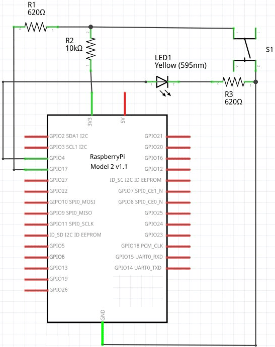
Now that we know how to properly connect LEDs and buttons to ports, we can assemble a simple test circuit that uses one button and one LED.
Fig. 7. Scheme of secure connection of the button and LED to the Raspberry Pi GPIO.
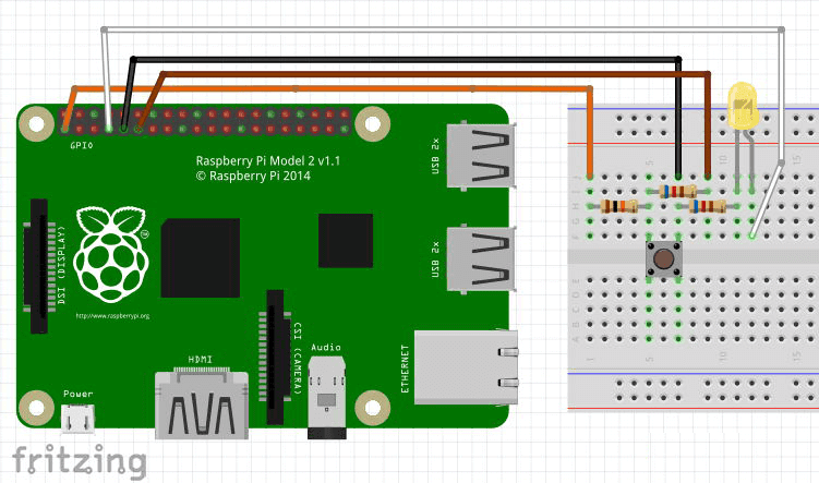
This scheme is quite simple to assemble as a wall-mounted installation, and using a solderless breadboard.
Fig. 8. The connection diagram of the switch and LED to the raspberry using a breadboard model.
Note: both of the diagrams shown above were drawn in a wonderful free program called “Fritzing”. You can download the program from fritzing.org for Linux, Windows, Mac OS X.
For those who use Debian GNU Linux, Ubuntu, Linux Mint to install the program, just run the command in the console:
sudo apt-get install fritzing
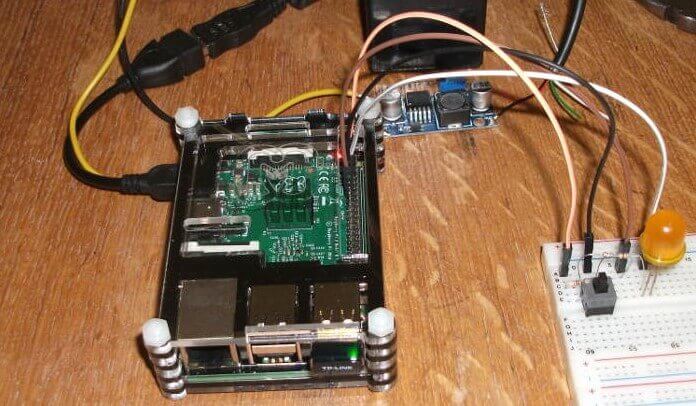
For this experience, I collected the same circuit, I took the LED that I found – yellow and big, a button from some PC system unit
Fig. 9. The layout of the experiment with the LED, button and Raspberry Pi GPIO.
For convenient remote programming and control, a wireless WiFi adapter is connected to the raspberry pi
The raspberry itself is powered by a step-down voltage stabilizer (LM2596S), a 6V and 6A * H battery is used as a power source. You can also power everything from a network power supply to 5V 2A, but I already had a test bench assembled with battery power, so I applied it.
RPi.GPIO module
To write the program, we will use the “RPi.GPIO” module, which contains a lot of different features for managing the Raspberry Pi GPIO.
In the Raspbian operating system, this module is installed by default, it just might not hurt to update it, for this we will execute the following commands in the raspberry console:
sudo apt-get update
sudo apt-get install python-rpi.gpio
Program for experimenting with LED and button
If you have already collected and double-checked everything, then we can proceed to writing the program. We will program in Python (Python) – this is a convenient, fast and feature-rich scripting programming language. After writing the program, you do not need to compile anything, just run the script for execution and admire the result.
The LED glow at the moment the button is pressed is the first thing that comes to mind, but it is somehow not at all interesting. We are implementing a program that will make the LED flicker at a frequency of 2 times per second (2Hz), and when the button is pressed, the flicker frequency will increase by about 5 times (10Hz) – I think that this example is more interesting than just pressing the button and lighting up the LED.
To run the program, you need to save it to a file and then upload it to the Raspberry Pi. To do this, you first need to connect to the raspberry remotely through the terminal (SSH) or open the Terminal program if you are working in the Raspbian OS graphical environment directly on your raspberry.
In the example below, we will work using the GPIO module from the RPi package.
To create a program file under the name “led_key_test.py” in the directory “/ home / pi” and then open it for editing in the editor, you need to run a simple command:
nano /home/pi/led_key_test.py
A text editor will open where you need to copy the following listing of the program:
#!/usr/bin/env python
# -*- coding: utf-8 -*-

# Connect the necessary libraries (for time delay and GPIO)
import time
import RPi.GPIO as GPIO

# Set the GPIO pin numbers with which we will work
LED =4
KEY =17

# Do a reset of port states (all are configured for input - INPUT)
GPIO.cleanup()
# Pin numbering mode - by name (not by serial number on the connector)
GPIO.setmode(GPIO.BCM)
# Configure pin LED to output (OUTPUT)
GPIO.setup(LED, GPIO.OUT)
# Set the low level (0) on the LED pin
GPIO.output(LED, GPIO.LOW)
# Configure the KEY pin for input (INPUT)
GPIO.setup(KEY, GPIO.IN)
# Display the greeting text
print 'Hello! Blink...blink...'

# Check for interruption of the program from the keyboard (CTRL + C)
try:
    # Perpetual cycle
    while True:
        # If the button is pressed (on the KEY pin, the low level is 0V)
        if GPIO.input(KEY) == False:
            # Set the delay to 0.1 seconds. and display a message
            timeout = 0.1
            print 'Key pressed.'
        else:
            # otherwise, the delay is 0.5 seconds.
            timeout = 0.5
        # We light up the LED connected to the LED pin
        GPIO.output(LED, GPIO.HIGH)
        # Let's wait (we will fulfill the delay set above)
        time.sleep(timeout)
        # We extinguish the LED connected to the LED pin
        GPIO.output(LED, GPIO.LOW)
        time.sleep(timeout)
# If the key combination CTRL + C was pressed - reset pins and end
except KeyboardInterrupt:
    GPIO.cleanup()
Important: in the program it is necessary to observe the indentation – each with 4 spaces or one tab, for example, after the “else” line starts with 3 tabs or 12 spaces, and before “while True:” – one tab or 4 spaces (1 tab = 4 spaces) . This is important and necessary for the program to work properly in Python!
To save the file and exit the editor, press CTRL + X, and when asked about saving the file, press the “y” key and confirm with “ENTER”.
Now we make our script executable and we can run our program, execute the commands:
chmod +x /home/pi/led_key_test.py
/home/pi/led_key_test.py
After starting, a greeting will be displayed on the screen, and the LED should start flashing at a frequency of about 2 times per second.
Fig. 10. Raspberry Pi GPIO test program for the LED and buttons, the result of work.
A short video demonstrating the operation of the program (18 seconds):
Monitoring the status of all Raspberry pi GPIO pins
For convenient monitoring of modes and levels on all GPIO pins, you can run the following command in the console:
gpio readall
As a result of the command, a detailed and visual tablet will be displayed in approximately the following form:
+-----+-----+---------+------+---+---Pi 3---+---+------+---------+-----+-----+
 | BCM | wPi |   Name  | Mode | V | Physical | V | Mode | Name    | wPi | BCM |
 +-----+-----+---------+------+---+----++----+---+------+---------+-----+-----+
 |     |     |    3.3v |      |   |  1 || 2  |   |      | 5v      |     |     |
 |   2 |   8 |   SDA.1 | ALT0 | 1 |  3 || 4  |   |      | 5v      |     |     |
 |   3 |   9 |   SCL.1 | ALT0 | 1 |  5 || 6  |   |      | 0v      |     |     |
 |   4 |   7 | GPIO. 7 |   IN | 0 |  7 || 8  | 0 | IN   | TxD     | 15  | 14  |
 |     |     |      0v |      |   |  9 || 10 | 1 | IN   | RxD     | 16  | 15  |
 |  17 |   0 | GPIO. 0 |   IN | 0 | 11 || 12 | 1 | IN   | GPIO. 1 | 1   | 18  |
 |  27 |   2 | GPIO. 2 |   IN | 0 | 13 || 14 |   |      | 0v      |     |     |
 |  22 |   3 | GPIO. 3 |   IN | 0 | 15 || 16 | 1 | IN   | GPIO. 4 | 4   | 23  |
 |     |     |    3.3v |      |   | 17 || 18 | 0 | IN   | GPIO. 5 | 5   | 24  |
 |  10 |  12 |    MOSI |   IN | 0 | 19 || 20 |   |      | 0v      |     |     |
 |   9 |  13 |    MISO |   IN | 0 | 21 || 22 | 0 | IN   | GPIO. 6 | 6   | 25  |
 |  11 |  14 |    SCLK |   IN | 0 | 23 || 24 | 1 | IN   | CE0     | 10  | 8   |
 |     |     |      0v |      |   | 25 || 26 | 1 | IN   | CE1     | 11  | 7   |
 |   0 |  30 |   SDA.0 |   IN | 1 | 27 || 28 | 1 | IN   | SCL.0   | 31  | 1   |
 |   5 |  21 | GPIO.21 |   IN | 1 | 29 || 30 |   |      | 0v      |     |     |
 |   6 |  22 | GPIO.22 |   IN | 1 | 31 || 32 | 1 | IN   | GPIO.26 | 26  | 12  |
 |  13 |  23 | GPIO.23 |   IN | 0 | 33 || 34 |   |      | 0v      |     |     |
 |  19 |  24 | GPIO.24 |   IN | 0 | 35 || 36 | 1 | IN   | GPIO.27 | 27  | 16  |
 |  26 |  25 | GPIO.25 |   IN | 0 | 37 || 38 | 1 | IN   | GPIO.28 | 28  | 20  |
 |     |     |      0v |      |   | 39 || 40 | 1 | IN   | GPIO.29 | 29  | 21  |
 +-----+-----+---------+------+---+----++----+---+------+---------+-----+-----+
 | BCM | wPi |   Name  | Mode | V | Physical | V | Mode | Name    | wPi | BCM |
 +-----+-----+---------+------+---+---Pi 3---+---+------+---------+-----+-----+
In order not to run the command each time waiting for the observed changes, you can use the “watch” utility, which will update the output of the “gpio readall” command with an interval of 1 second (parameter “-n 1”):
watch -n 1 "gpio readall"
How to manage GPIO pins in any programming language
The GPIO interface, like other devices in Linux, is presented in the form of directories and device files that can be accessed for reading, as well as recording the necessary values thereby changing the configuration and state of the port pins. This system is called SysFS (System File System), a virtual file system provided by the Linux kernel.
Let’s conduct a brief experiment, light up and turn off the LED that is connected through the quenching resistor to pin number 15 (GPIO22). To do this, tell the driver that we will work with the GPIO22 pin, reserve the port for the duration of the operation (other applications will not be able to use it until we release it). This is done using the command:
echo 22 > /sys/class/gpio/export
Using the following command, see if a file has been created for our GPIO22:
ls /sys/class/gpio/
We will see something like this list:
export gpio22 gpiochip0 unexport
Our pin is ready to work – a folder called gpio22 has appeared. We can also see what files in the folder the Linux kernel created for our pin (they can be accessed – write and read information from the port):
ls /sys/class/gpio/gpio22
At the output of the command we get:
active_low device direction edge subsystem uevent value
And now, using the following command, set the direction (direction) of the GPIO22 pin to the output (OUTPUT) and immediately look at the second command whether everything was installed as it should:
echo out > /sys/class/gpio/gpio22/direction
cat /sys/class/gpio/gpio22/direction
As a result, the word “out” should appear on the screen, which indicates that everything is installed correctly. Now it remains only to apply a high level to our pin to illuminate the LED. Let’s make it output the number 1 to the file /sys/class/gpio/ gpio22/ value, use this command:
echo 1 > /sys/class/gpio/gpio22/value
The LED should light up. You can read the pin status using the command:
cat /sys/class/gpio/gpio22/value
And now we turn off the LED – execute the command:
echo 0 > /sys/class/gpio/gpio22/value
Well, lastly, after all the useful work done, we will release the GPIO22 pin, make the driver unregister it:
echo 22 > /sys/class/gpio/unexport
In this way, you can communicate with GPIO using regular requests to text files, you can write scripts in any language and for any task. It is important to remember that after reserving a pin (export) and performing work related to it, you need to reserve it (unexport), otherwise it will remain busy and other programs and scripts will not be able to access it!
Raspberry pi RPIO module
In the above experimental program, we used the GPIO module from the RPi package. There is another interesting module that deserves attention – this is RPIO .
RPIO is a module with additional features for working with Raspberry Pi GPIO. It contains all the functionality of the GPIO package (RPi) and some additional features.
Also, this module contains two useful and convenient console utilities:
rpio-curses – a convenient console graphical interface for monitoring and setting pin states;
rpio is a console utility for setting pin states, monitoring pin states and their modes, as well as for receiving other useful information.
Conclusion
I hope it was not boring and the information that I presented in this article will be useful for your future projects and experiments with the Raspberry Pi platform.
What can be done after the LED and the button? – you can connect three LEDs and make a small running fire, and instead of the LED, you can connect a key transistor and a small-sized electromagnetic relay to turn on and off various devices powered by + 12V or ~ 220V. The number of options is limited only by your imagination and desire.





Leave a Reply