
Raspberry Pi GPIO input wired with button

Basically, you can operate a GPIO pin either as an input or as an output. As an input, it can assume the states “High” and “Low”. For example, from a switch or button.
In general, Raspberry Pi’s GPIOs are wired with resistors to set inputs to a defined level (+ VCC or GND) or to limit the current.
- Basics: Connect Raspberry Pi GPIO
GPIO input with push-button / switch and pull-up resistor
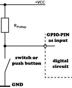
The pullup principle pulls the GPIO input to the + VCC level with a pull-up resistor. The ground state of the input would then be “high” or “logical 1”. With a switch or pushbutton, the GPIO input is pulled or switched to ground (GND). That is, in the switched state, the input would have the state “Low” or “logical 0”.
GPIO input with push-button / switch and pull-down resistor
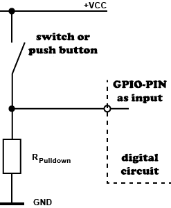
The pull-down principle pulls the GPIO input with a pulldown resistor to ground (GND). The ground state of the input would then be “low” or “logical 0”. With a switch or pushbutton, the GPIO input was pulled to the level of + VCC. This means that in the switched state, the input would have the status “High” or “Logic 1”.
GPIO input with button / switch and cross resistance

Basically, the current in the switched state (push button / switch actuated) is limited only by the resistance of the internal components. In order to limit the current in the external wiring, an additional shunt resistor is often switched in front of the GPIO input.
Pull-up or pull-down resistor?
It is recommended to connect GPIO inputs with a pull-up or pull-down resistor. The question is, why is such a resistance necessary? And which principle should be used? So pullup or pulldown? And what size should these resistors have?
Leave a Reply