
NodeMcu is an ESP8266 based platform for creating various Internet of Things (IoT) devices. The module can send and receive information to a local network or to the Internet using WiFi. An inexpensive module is often used to create distance-controlled smart home systems or Arduino robots. In this article, we will look at the board description, version differences, and NodeMcu v3 pinout the latest version of the NodeMcu Esp8266 module . We will also briefly review the Lua language in which you need to write programs for NodeMcu.

Description of ESP8266 NodeMcu v3
Technical characteristics of the module:
- Supports Wi-Fi protocol 802.11 b / g / n;
- Supported Wi-Fi modes – access point, client;
- Input voltage 3.7V – 20 V;
- Operating voltage 3V-3.6V;
- Maximum current 220mA;
- Built-in TCP / IP stack;
- Operating temperature range from -40С to 125С;
- 80 MHz, 32-bit processor;
- Wake up time and send packets 22ms;
- Built-in TR switch and PLL;
- The presence of power amplifiers, regulators, power management systems.
There are several generations of NodeMcu boards – V1 (version 0.9), V2 (version 1.0) and V3 (version 1.0). Designations V1, V2, V3 are used when selling in online stores. Boards often get confused – for example, V3 is outwardly identical to V2. Also, all boards work on the principle of open-source, so they can produce any company. But Amica, DOIT and LoLin/Wemos are currently producing NodeMcu boards.
Differences from other modifications
Boards of generation V1 and V2 are easy to distinguish – they have different sizes. Also, the second generation is equipped with an improved modification of the ESP-12 chip and 4 MB of flash memory. The first version, outdated, is made in the form of a bright yellow platform. It is inconvenient to use it, since it covers 10 outputs of the breadboard. The second generation board was made to correct this drawback – it has become narrower, the outputs are well suited to the board contacts. V3 boards look no different from V2; they have a more reliable USB output. The LoLin company releases the V3 board, one of the differences from the previous board is that one of the two reserved outputs is used for additional ground, and the second for USB power supply. The board also has a larger size than previous types.
Where to buy NodeMCU and ESP8266 modules
Today, there are many fairly inexpensive modifications of the ESP8266-based boards available on the market. We made a small selection of the most interesting options:

Power NodeMcu Module
There are several ways to supply power to the module:
- Supply 5-18 V through Vin;
- 5V via USB or VUSB pin;
- 3.3V via 3V pin.
Benefits of NodeMcu v3
- The presence of a UART-USB interface with a micro USB connector makes it easy to connect the board to a computer.
- The presence of flash memory at 4 MB.
- Ability to update firmware via USB.
- Ability to create scripts on LUA and save them in the file system.
Disadvantages of the NodeMcu module
The main disadvantage is the ability to execute only LUA scripts located in RAM. This type of memory is small, the volume is only 20 KB, so writing large scripts causes a number of difficulties. First of all, the whole algorithm will have to be divided into linear blocks. These blocks must be written to separate system files. All of these modules are executed using the dofile operator.
When writing, you must follow the rule – when exchanging data between modules, you need to use global variables, and when calculating inside modules, you need to use local variables. It is also important to call the collectgarbage function (garbage collector) at the end of each script you write.
Nodemcu v3 datasheet
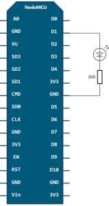
nodemcu V3 module has 11 general-purpose I/O pinout. In addition, some of the conclusions have additional functions:
- D1-D10 – outputs with pulse-width modulation;
- D1, D2– pins for the I²C / TWI interface;
- D5 – D8 – pins for the SPI interface;
- D9, D10 – UART;
- A0 – input from the ADC.

How do I connect to NodeMCU?
To get started with NodeMcu, you need to connect the board to the computer. The first step is to install the CP2102 driver and open the Arduino IDE. Then you need to find in the “File” – “Settings” and in the “additional links for the board manager” window insert the link http://arduino.esp8266.com/versions/2.3.0/package_esp8266com_index.json
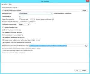
After that, in the menu “documents” – “board” “board manager” select “esp8266” and install the latest version. After the done actions in the menu “tools” – “board” you need to find NodeMCU.
After all the necessary data is installed and copied, you can start working.
Nodemcu esp8266 examples
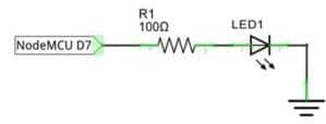
An example of connecting an LED to NodeMCU schematic
The schematic diagram of the connection is shown in the figure.
The final layout of the layout is as follows:

The board itself runs on 3.3 V, so you need to use a resistor to connect the LED. In this example, a 65-ohm resistor is taken for the red LED.
In a similar way, a photodiode is also connected to the board:

The NodeMCU V3 board can also be used for IR control. To control you need a remote control with an IR receiver and the platform itself. The infrared receiver is connected as shown below:

Firmware for esp8266 NodeMcu
The platform is loaded with the standard Node MCU firmware, in which the Lua language interpreter is integrated. Using Lua commands, you can do the following:
- Connect to a Wi-Fi access point;
- Work as a Wi-Fi access point;
- Switch to deep sleep mode to reduce energy consumption;
- Turn on or off the LED on the GPIO16 output;
- Perform various operations with files in flash memory;
- Search for an open Wi-Fi network, connect to it;
- MAC address output;
- Manage user timers.
For programming NodeMCU, you can use the Arduino IDE or the SDK development kit – ESPlorer. This complex has several differences:
- It can work on many different platforms;
- It has support for multiple open files;
- Allows highlighting the Lua language code;
- The ability to smartly send files;
- The ability to support several types of firmware at the same time.
To ensure correct and stable operation, you need to update the firmware to the latest version. There are several upgrade methods – cloud service, Docker Image, and compilation on Linux. Each of these methods has its pros and cons. The simplest and most understandable is the first method.
Collecting firmware in the cloud service
Cloud service has a simple and convenient interface. Work begins with an email. Next, you will be prompted to select the type of firmware – stable firmware or tested. The first is used for training and creating a large number of objects, so it is recommended to choose it. The next step is to connect the necessary modules. By default, several key points have already been recorded, the rest should be included only if necessary. Then additional options are selected. Among them there is FatFS support for reading an SD card or turning on debugging mode.
After the start of the assembly, a letter will arrive in the mail signaling the start of the process. After a while, the second letter will come – it will be offered to choose the version of float (fractional numbers) or integer (integers).
After clicking on the received link, you will need to download the bin file and place it in Resources – Binaries. The nodemcu_integer_0.9.5_20150318.bin file will be located there, which must be deleted. As a result, the contents of the folder will look as follows.

NodeMcu Firmware Update
For the correct and stable operation of the board, you need to overwrite esp_init_data_default.bin. You can download it on the official website. The necessary file must be put back into the NodeMCU Flasher firmware system along the Resources – Binaries path, having previously deleted the old file from it.
Then you can connect NodeMCU and proceed with the upgrade. First you need to change the settings – in NodeMCU Flasher, in the Config tab, you need to select the assembled firmware file instead of INTERNAL://NODEMCU.

Leave the rest unchanged, go to Operations and click Flash. As soon as the firmware finishes, you need to switch to Config again and specify the path esp_init_data_default.bin in the first line. The address where you want to move this file is also indicated. For NodeMCU, select address 0x3FC000. After that, you need to return to Operations again and click Flash.
After that, you need to reformat the entire file system. To do this, run ESPlorer, be sure to set the exchange speed to 115200 and restart NodeMCU. After all the above steps there will be a new firmware version. The debug board is completely reflashed and ready to work.
Short description of the Lua language
Lua has a simple syntax and powerful data description constructs based on arrays and extensible semantics. This powerful programming language is used to create software, expand various games. Unlike other languages, Lua has more flexible and more powerful designs.
Flashing LED on Lua
You can consider the simplest scheme – blinking LED. This example will help you learn how to work with GPIO pins. The LED must be connected as shown in the diagram.
Then you need to write the following sketch to the left window of ESPlorer:
pin_number = 1
gpio.mode (pin_number, gpio.OUTPUT) //setting the operating mode to the output
gpio.write (pin_number, gpio.HIGH) //high level setting
gpio.write (pin_number, gpio.LOW) //low level setting
gpio.serout (1, gpio.HIGH, {+990000,990000}, 10, 1) //set the LED to blink 10 times
After that you need to save the script called init.lua. Immediately after this, the written code will be automatically loaded into the debug board and executed. If the operation is successful, the debug board will blink with an LED.
It is important to note that the board runs the script on its own, the connection to the computer is necessary only for power supply.
Leave a Reply