
Raspberry Pi connect GPIO with pull-up or pull-down resistor

You can optionally use GPIOs as inputs and outputs. Of course, depending on their configuration. It is recommended to connect GPIO inputs with a pull-up or pull-down resistor.
For this we clarify several basic questions:
- Why does a GPIO input need a pull-up or pull-down resistor?
- What is the behavior of a GPIO input without resistance?
- What is the behavior of a GPIO input with pullup resistor?
- What is the behavior of a GPIO input with pulldown resistor?
- What values should pullup and pulldown resistors have?
- Why should not a pull-up or pull-down resistor be less than 10K ohms?
- Why should a pull-up or pull-down resistor be less than 10K ohms?
- Which principle should be used? Pullup or pulldown resistor?
- Should I use the internal pull-up / pull-down resistors of a GPIO input?
1. Why does GPIO input need a pull-up or pull-down resistor?
If you configure a GPIO as an input, then the GPIO input that is still unconnected does not yet have a fixed state. That is, it is not necessarily high or low. CMOS inputs, such as GPIO inputs, tend to be high (1). But you can not rely on that. GPIO inputs tend to switch randomly one way or the other. That is, they sometimes have the state “Low” (0) and sometimes the state “High” (1). And that depends on what the respective pin or connection point just captures. The influential spectrum ranges from high-frequency interference of surrounding components and pins, to overvoltage. In general, these are the unwanted effects that cause that the state of a GPIO input jumps completely undefined between “high” and “low”. This has the disadvantage that when you evaluate a GPIO input, you can never be sure which state it really has.
To counteract this, a GPIO input is helped to a defined ground state. In practice, you provide the respective pin with a pull-up or pull-down resistor. Depending on whether the state “high” or “low” is expected by default.
“Pull” means “pull”. This means that the GPIO is “pulled” to a certain level (voltage value). Pullup means to move up and pull down to low. Pulling up can be achieved by connecting the GPIO pin to a pin through a resistor that will permanently carry a high level. As a rule, the operating voltage + VCC is used for this purpose. Pulling down can be achieved by connecting the GPIO pin to ground (GND) through a resistor.
Note: Raspberry Pi also has internal pull-up/pull-down resistors, which are normally disabled. It is better, you use external resistors. You can see that and then know that the GPIOs are properly connected.
Outputs can also be wired with pull-up/pull-down resistors. However, their meaningfulness depends on the subsequent circuit part. This circuit part also has inputs which should have levels defined in the ground state. This means that additional pull-up/pull-down resistors can also be found between different circuit components and components.
2. What is the behavior of GPIO input without resistance?
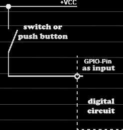
What happens if we work without pullup and pulldown resistors?
Switch open
The GPIO input has no connection to anything. He practically hangs in the air. The wire from the pin to the switch acts like an antenna. And this antenna receives something. Of course, the input electronics can not do anything with this and swing undefined between “low” (0) and “high” (1) back and forth.
Switch closed
The GPIO input is pulled to VCC. The input electronics recognize a “high” (1).
effects
In practice, this means that if the state of a GPIO input is queried on the software side and detects a closed switch, then it can also be open. And of course you just want to avoid this uncertainty. And that is why GPIO inputs must always be wired with a pull-up or pull-down resistor.
3. What is the behavior of GPIO input with pullup resistor?
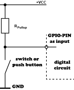
In this diagram, the resistance of VCC is switched to a GPIO input and the open switch is switched from GPIO input to GND.
The circuit diagram of raspberry pi pull up resistor and switch can also be thought of as a series connection of two resistors. The voltage and current distribution apply accordingly. Wherein the switch in the open state is an infinite high-impedance and in the closed state, a low-resistance.
Switch open
When the switch is open, the resistor pulls the GPIO input towards VCC. Here are definitely z. B. +3.3 V, so “high” to. And that’s why this resistance is called pullup resistance. Because the resistor pulls the GPIO up to the operating voltage.
Switch closed
When the switch is pressed, the GND is connected to the GPIO input. This has the following effect: The voltage drops completely at the pull-up resistor and thus lies at the GPIO input GND and thus a “low”.
4. What is the behavior of GPIO input with pull-down resistance?
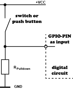
In this diagram, the open switch is switched from VCC to the GPIO input and the resistance from the GPIO input to GND.
The circuit diagram of pull-down resistor and switch can also be thought of as a series connection of two resistors. The voltage and current distribution apply accordingly. Wherein the switch in the open state is an infinite high-impedance and in the closed state, a low-resistance.
Switch open
When the switch is open, the resistor pulls the GPIO input towards GND. Here is definitely 0 V, ie “low” on. And that’s why this resistance is called pulldown resistance. Because the resistor pulls the GPIO down to 0V.
Switch closed
When the switch is pressed, VCC is connected directly to the GPIO input. This has the following effect: The voltage drops completely at the pulldown resistor and thus is at the GPIO input VCC on and thus a “high”.
5. What values should pullup and pulldown resistors have?
How big the resistances should depend on the application. Normally, values of 10 to 100k Ohm are suitable. So you do not necessarily have to take the often recommended 10k Ohm resistors. It may be more. That’s clever if you do not have the right resistance.
There is even a strong case for using a value greater than 10k Ohm. For example, the internally switchable pull-up and pull-down resistors are between 50 and 65k Ohm. One should orientate oneself on that. A resistance value of 10k Ohm is therefore to be understood as a lower value.
A higher resistance than 10k Ohm is especially necessary if Raspberry Pi is powered by battery, battery or solar. Then it comes down to the lowest possible power consumption and then you should perhaps use greater resistance values than 10k Ohm. Namely, if in the ground state current over a too small pull-up or pull-down resistance flows, then this is at the expense of power consumption and reduces the running time.
Example calculation: With a VCC of 3.3 V and a pull-up resistor of 10k Ohm, 0.33 mA flow through the resistor to the GPIO input in the default state. That is not much. But with a higher resistance, you can cut power consumption even further. For example, with 1 MOhm. But, then you have to make sure that the contacts and pins are protected against dust because otherwise, the contact resistance at the pins leads to a voltage divider between pull-up / pull-down resistor and contact resistance. In such a case, one can search for the error for a long time.
6. Why you should not a pull-up or pull-down resistor be less than 10K ohms?
If a switch-resistor combination is used when wiring a GPIO input, then in the ground state (open switch) only a current flows through the resistor. Now, when the switch is actuated, the voltage across the resistor and the closed switch is split. Since the closed switch in the optimum case has 0 ohms, there is no voltage drop. Now it is the case that a switch never has zero ohms. At the low contact resistance of the switch contacts always falls from a voltage that is barely measurable and therefore can be neglected in the rule.
But if the contact resistance of the switch contacts is too large and the pull-up or pull-down resistance is too small, then the ratio of the partial voltages to the resistor and switch may change unfavorably. Under certain circumstances, the level for a high or a low is not reached. Especially with small voltages and currents, you should consider that something like this can happen.
7. Why you should a pull-up or pull-down resistor be less than 10K ohms?
In general, a resistance of at least 10k Ohm or more is recommended for pull-up and pull-down resistors. Now, with larger pull-up or pull-down resistors, the susceptibility to faults at switches also increases.
The reason is that in harsh environments with dust generation, frequently changing temperature, and high humidity due to chemical processes, the nature of metallic surfaces changes. Oxidation or corrosion can increase the electrical resistance of metal contacts and junctions.
This is not a problem if we are dealing with a protected environment in which Raspberry Pi and its external circuitry are protected from outside influences.
Nevertheless, some electronics practitioners recommend working with pull-up and pull-down resistors under 10k Ohm down to 1k Ohm. The idea is that a significant current through the switch contacts breaks through the deposits. The stream cleans the contacts, so to speak. If the currents are too low, the deposits on the switch contacts will remain and lead to a higher contact resistance and thus to errors in detection of the switch state. Furthermore, a current of a few mA much more likely to swallow glitches from the outside, as a current of only a few microamps.
8. Which principle should be used? Pullup or pulldown resistor?
The question is, if one has the choice if one applies Pullup- or Pulldown-Prinzip, thus against Ground (GND) or + VCC switches, which variant one should prefer?
The short answer: From a certain point of view, that is a philosophical question. It does not really matter. However, the practical electronics and thus the wiring of GPIOs has some pitfalls, which is why it may play a role. And that’s why the long answer follows.
If you have the choice whether to switch to GND or VCC, then this is a question of interference immunity. In practice, one tends to connect GPIO inputs with a pull-up resistor to + VCC and switch it to Ground (GND).
Reason: With the pull-up principle, that is, resistance to VCC, all circuit parts are referred to GND. So you have the lowest impedance level that the circuit can get. If this GND is a printed circuit board or a surface (tarpaulin) on a circuit board, then this also has the advantage, among other things, that hardly any unwanted current loops can form in the external wiring with the printed circuit board. Except, you work with very high frequencies.
If a GND intercepts an interference signal, then this has (almost) no influence on the rest of the circuit. Additional ceramic capacitors between VCC and GND provide the same potential.
With the pull-up principle, you are allowed to do something stupid. For example, an unfavorable wiring from the switch to the GPIO pin.
The pull-down principle is different. Here there is a much higher risk, because an external interference signal can influence the VCC and different tracks exist for VCC. That is, a VCC can catch a glitch rather than a GND. To make matters worse, that you can not see what is going on in case of failure.
By using capacitors between VCC and GND, as well as parallel to the switch, one can keep the sensitivity of VCC low by momentary glitches. Nevertheless, if you want to be on the safe side, then the pull-up principle is recommended.
And now we come to the everyday small electronics reality. Let’s start with a relatively small device, in which the entire circuit consists of a button or switch function. For example, if you connect the GPIOs of a Raspberry Pi. Here, hardly any critical faults are to be expected from adjacent components or printed conductors. Because they are not connected, for example. In such a case it is completely irrelevant whether the pull-up or pull-down principle is applied.
You only get a problem if you work with longer line between switch and GPIO pin. And then it depends on where these lines lead. If z. For example, if a 230VAC cable is nearby and a lamp is turned on and off at the end of the cable, then steep voltage edges will be created in this cable during switching. The scatter as a short needle pulses in the supply of the button or switch to the GPIO. An open contact may cause false triggering because this pulse is routed to the output of the GPIO front-end.
This can be avoided by using a ceramic capacitor (Kerko) in parallel with the switch or button with a value of 100 nF. In combination with a pull-up resistor of 10k Ohm this gives a time constant of 1 ms. This is enough to block fine needle pulses that are in the range of μs and below.
Capacitor and resistor should be as close as possible to the GPIO. Especially the capacitor. At the switch or button, the capacitor brings nothing. Especially not with a long line.
So golden Raspberry Pi GPIO rule applies: If we just connect a simple switch on Raspberry Pi GPIO to internally change the state between “high” and “low” (a program evaluates this state). Then take a pullup resistor and switch to GND.
Since the basic state of the GPIO input is then usually “high” or “1”, it is switched to “low” or “0”. Then you have to negate this in the evaluating program or source code, if the default state should be “Low” or “0”.
9. Should I use the internal pull-up / pull-down resistors of a GPIO input?
All GPIOs have an internal, software-selectable pull-up or pull-down resistor of 50 to 65k Ohm. Exceptions are pins 3 and 5 (GPIO 2 and GPIO 3). These are the pins for SDA and SCL of the I2C bus. These are physically connected with 1.8k Ohm fixed with pull-up resistors, which can not be switched off.
In general, it makes sense to obstruct real resistors in the circuit. Because you do not forget to switch on the software side. The problem with this is that you cannot be sure that this always works and in any case. If an input circuit relies on it, it may cause a malfunction if the resistor is missing. In that sense, it is better to use external resistors. As you can see that they are available.
If you want to switch on the internal resistors, then you have to take into account that external resistors, which are connected in parallel, in the sum lead to a different total resistance.
When connecting resistors in parallel, the following rule applies: The total resistance of the parallel connection is smaller than the smallest partial resistance. This means that a parallel resistor always causes the current to increase. Furthermore, with two identical partial resistors, the total resistance corresponds to half of a partial resistance.
This does not mean that the wiring is faulty, but that the assumptions that have been made are not correct and can lead to a malfunction if the wiring is already on the verge of feasibility.
Leave a Reply