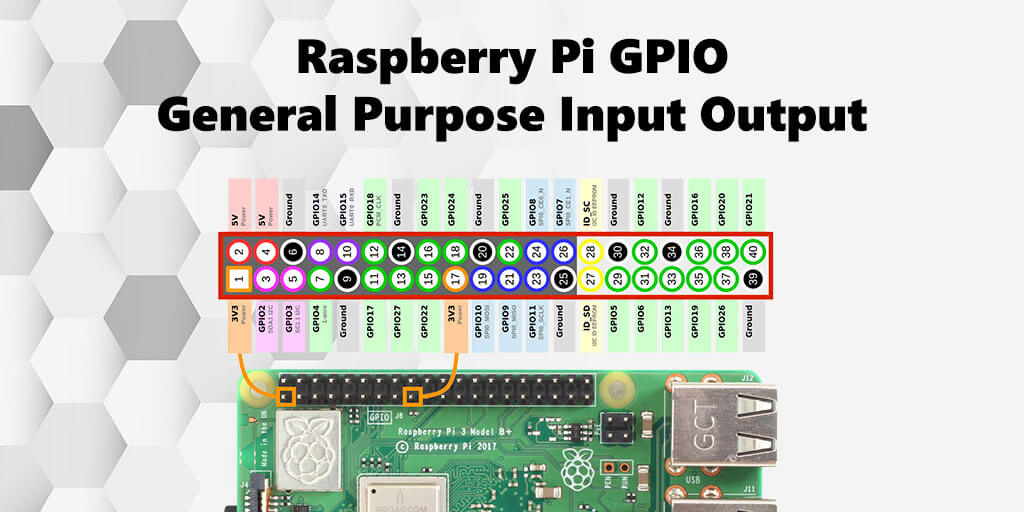
Raspberry Pi GPIO is the abbreviation for General Purpose Input Output. This designates programmable inputs and outputs for general purposes

The gpio are led out as a solder pin or pin in the form of a pin header and serve as an interface to other systems or circuits to control them via Raspberry Pi. When programmed, Raspberry Pi can accept digital signals from outside (input) or send signals to the outside (output).
Many of the GPIOs have different functions depending on their setting and programming. In addition to the typical GPIO inputs and outputs, there are also pins with the dual function for I2C, SPI and a serial interface.
Raspberry Pi GPIO assignment
Raspberry Pi GPIO assignment The GPIOs are often only as solder points, led out in Raspberry Pi advantageously as a pin header. Depending on the model, a Raspberry Pi has a pin header with 26 or 40 pins, although not all of them are for input or output. Some pins carry a + 5V, + 3.3V or 0V potential.
The function of many pins are flexible, some even double occupied. That is, before using them you have to assign a function to them by programming. In any case, before using a GPIO its function must be initialized. Excluded are the potential-leading pins. Their tension is always fixed.
Electrical Properties
The GPIO pins have multiple electrical properties that can be confusing to electronics novices. However, it is generally the case that all electrical systems have electrical properties that must be taken into account because they are often parameters and limits that determine the function and functioning of the electrical system. Or simply put, the consideration of the electrical properties of each electronic component decides whether a circuit will work or not. Or whether the system is damaged after commissioning and then has a defect.
Basically, Raspberry Pi is powered by 5 volts. However, the system works on chip based on 3.3 volts, which means that even the GPIOs work with 3.3 volts. Both input and output.
Furthermore, a GPIO tolerates only a few milliamperes (mA) of current. Depending on the source of another value is mentioned. One speaks of a maximum of 16 mA. Wherein inputs and outputs switch safely with 0.5 mA. If you want to have it simple in the sizing, then you can count on 1 or 2 mA. Depending on the wiring you should not pull more than 8 mA from a GPIO.
The pinout of the GPIO pin header also has + 5V pins, which serve to provide a + 5V potential when external circuitry requires them. However, the current drain is also limited here. Total 50 mA for all GPIO pins together.
This means that you cannot rate external circuits via a GPIO pin. They must have their own power supply. For example, by a second USB power adapter or a USB power supply with a second USB port.
Control Raspberry Pi GPIO outputs and inputs via a web server
For example, if you use web servers to access scripts that control the GPIO pins, then it may not work, even though the scripts are called work on the command line. This is because there is a separate user group named “gpio” to access the GPIOs. One likes to stumble over it, because one executes on the command line the scripts with the user “pi” and which is already in the group “gpio”, thus entitled to the execution of the scripts.
The user of the webserver is not “pi”, but usually “www-data”. For a script called via this user to control the GPIOs, this user must be in the user group “gpio”.
sudo usermod -G gpio -a www-data
Then you have to restart the webserver.
Power supply Raspberry Pi via GPIO
Many Raspberry Pi have died already, because handicrafts at the GPIO pins were not connected correctly. A single GPIO pin provides a maximum of 16 mA. All GPIO pins together at most 50 mA. Assuming the B + model of 40 GPIO pins, of which only 26 can be connected as inputs and outputs, then is the current that you can pull out of a GPIO pin, if you use all at the same time as an output, at less than 2 mA.
Since not all pins will be used as output at the same time, the current drain per pin should not be higher than 3 to 5 mA. The less, the more pins you can use as the output and the more stable the whole thing will be.
In general, it is enough to work with a current of 0.5 to 1 mA at a GPIO output.
Note: The GPIO pins are suitable for switching, but not for powering external circuit parts. They need their own power supply. For example, by a second USB power supply. Or a USB power supply with a second USB port.
Security Alert
If you connect the pins, then you should make sure that the pins are wired according to their function. So an input as input and an output as output. If you connect two outputs and one is at 0 V and the other at 3.3 V, then a current flows from output to output. This is equivalent to a short circuit, which can permanently damage the GPIO.

Leave a Reply